Week 20
First try to import a extremely rudimentary version of the model in the simulation environment. Or rather a simulation of the simulation (just running the model on a single computer and without connecting flight controls or visuals). Since the data is only from a single point (speed) this means that it only works well around mach 0.5, everywhere else the results is expected to be useless. This was more to test the process. We concluded two things.
- I will probably have to do most testing with Matlab on my own computer
- Hopefully I can get access to a computer with flight controls and a connected visual system and access to the aer-files (meaning I can exchange the data for the example model with the data for the Global 6000), but I cant really create a new data set with new filenames etc.
The next step will be to first create a dataset for the entire envelope (or at least expand the current data-set) and create a better approximation of the engine performance. Now I just used the reference thrust for all speeds and altitudes. This in combination with using only the drag coefficient for M0.5 resulted in basically a rocket. The last part will try to be to estimate the contribution of the radar on the drag coefficient.
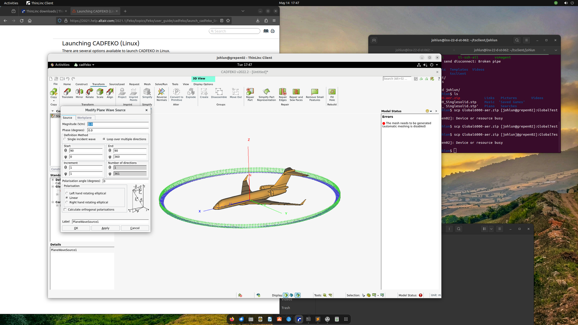
I've also started running the calculations for Radar Cross Section/Signature (RCS). I've had help setting up the calculations and running them. Even though I have access to a server with 96 CPU's it still took about 16 hours. The hardest part will be to try the explain the theory behind the calculations and converting the results to the format used in the simulation environment. After reviewing the files I haven't really seen an straight forward way to import the data into for example Matlab so I can rearrange the data.
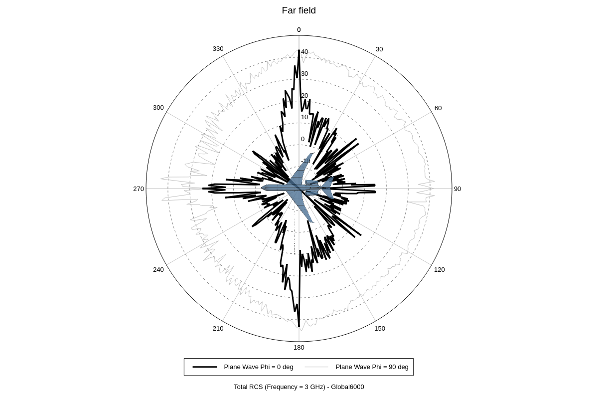
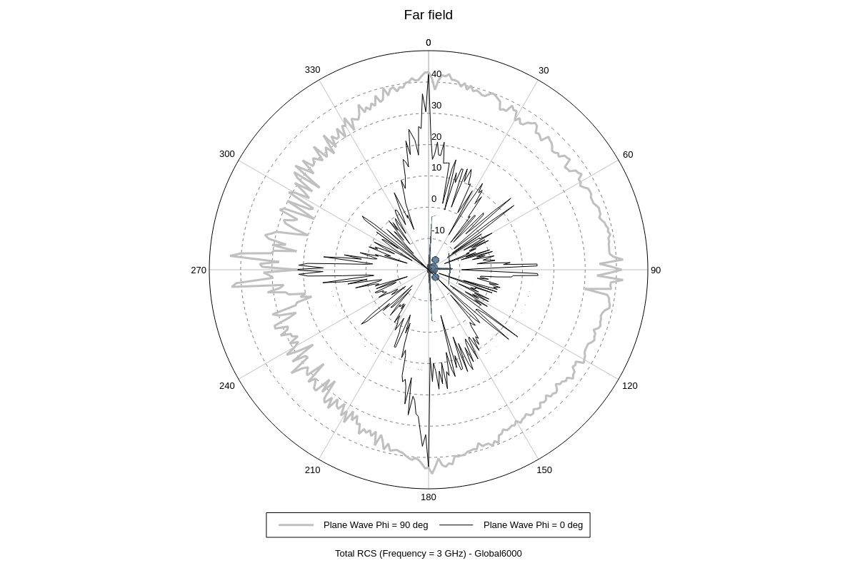
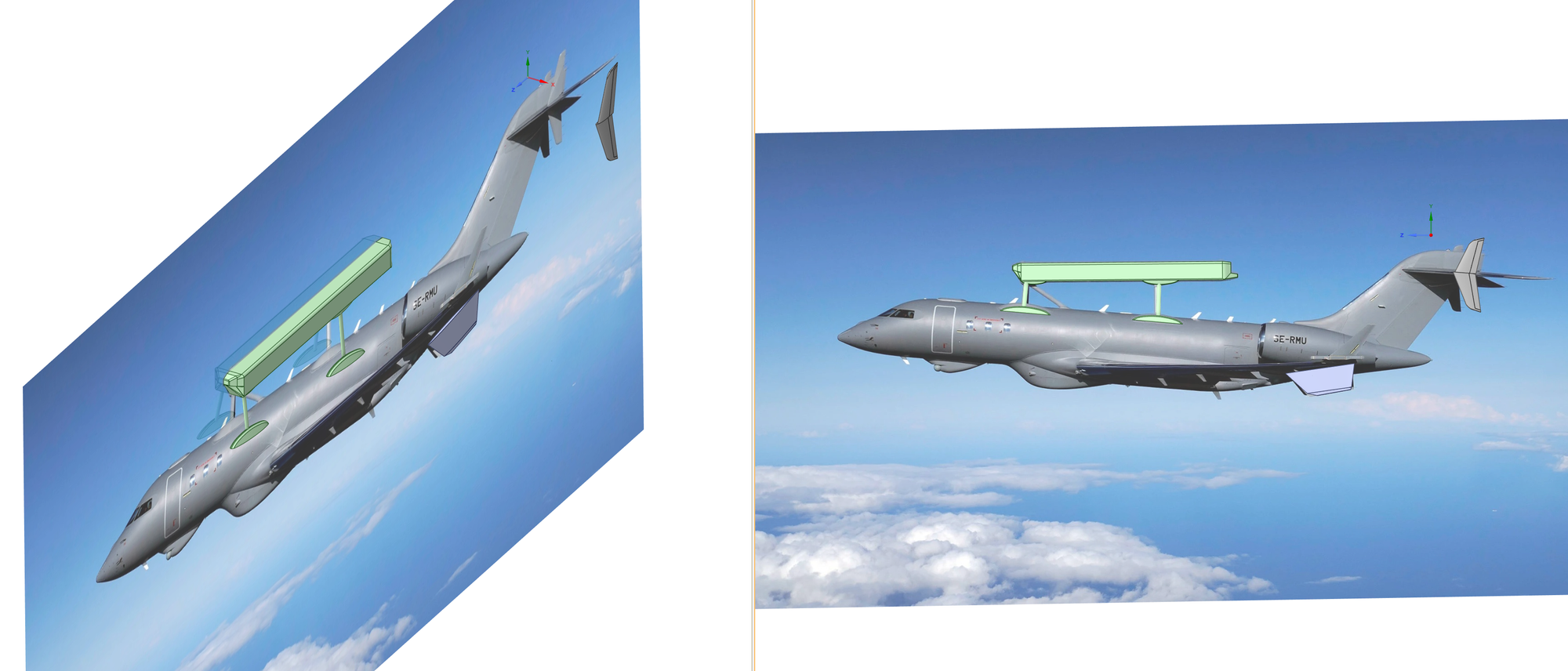
The calculated RCS for different angles, both plots show the same thing. The only thing that differs is that the thick line is connected to the current angle of the aircraft (as shown with the picture of the aircraft). If we assume the transmitting/receiving radar is in the horizontal plane around the aircraft, the black line show the corresponding RCS for every aspect angle if the aircraft flies horizontal. The grey line on the other hand will be if the aircraft pitch up 90 degrees (cobra maneuver? Or thrust-to-weight ratio of one and balancing?)
Week 19
This have been the week of DATCOM.
This week the focus have been on implementing a working model of the Global 6000 into DATCOM. This is a pretty impressive software (and free) but the original handbook(s) is from the 70's and was at the same time digitalized in FORTRAN. So that code is somewhat ancient. I have opted to buy a version called DATCOM+ which have some life enhancing improvements I think is well worth the price of the software. One advantage with Datcom+ compared to the free version is that it provides more specific errors and also a 3D-view of the aircraft and 2D-profiles for the airfoils and fuselage.
It is still code from the 70's though, so there is no GUI, just throw in a text file and run the command and hopefully the code will return the results without any errors (not likely on the first try).
There is a plugin called Aircraft Intuitive Designer (AID) for MATLAB that could help out somewhat in designing, it has a GUI and can overlay drawings of the aircraft. However it is quite buggy, and for the DATCOM input geometry it seems to work so-so. For example, after generating my design in AID and running it with DATCOM+ the wing was just a flat plate, and the fuselage was very boxy compared to the model in AID and the engines were missing.
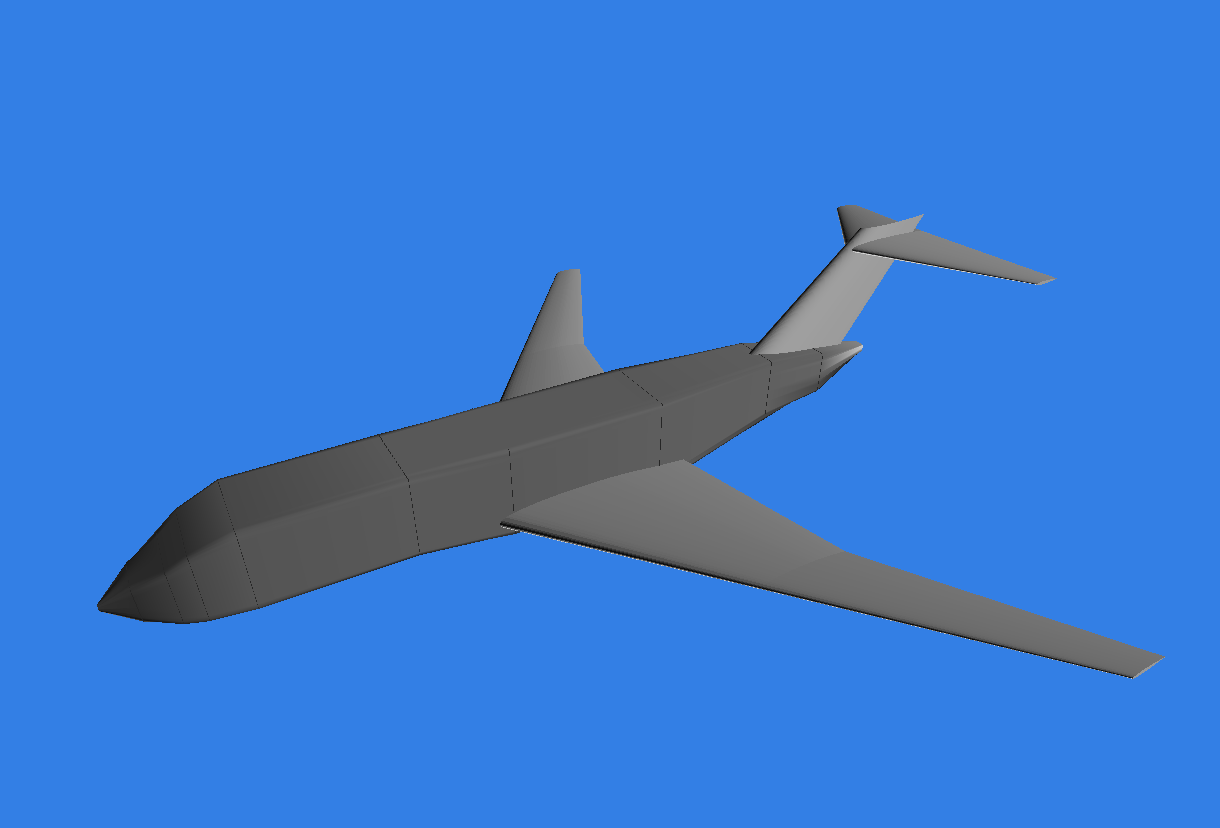
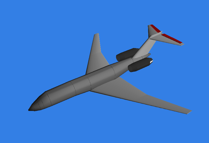
The AID version to the left compared what DATCOM "saw" of it to the right. In the middle picture I had fixed the wings from flat plates to the correct profile. The final version to the right, with smooth fuselage and elevators (and engines).
Week 15-18
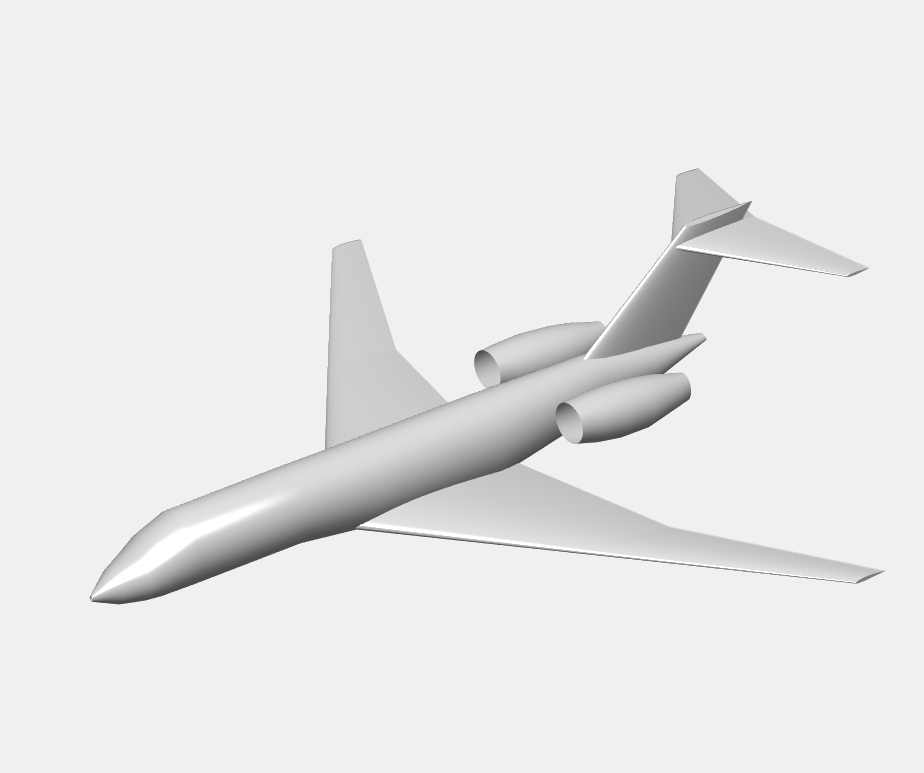
What have I actually done?! It has been four weeks since the last update, and it feels like I have nothing to show for. But if I try to remember what I have done is a sort of complete revamp of the CAD-model. From a distance everything looked perfectly fine, but upon closer inspection there were gaps, unsymmetrical parts and weird leftovers from the original model that made it impossible to create a single solid out of the model (which is needed for the radar cross section analysis).
I solved it by downloaded a 3D-model (not a parametric CAD-model, but probably intended for 3D-printing) of a Global 6000 and used Ansys SpaceClaim to trace the outlines of the mesh of the 3D-model to a solid which gave me a more accurate fuselage representation than before. The wings and empennage were unusable, both due the trace function just being able to trace the underside of the wings and also due to the fact that the model was intended for 3D-printing and the lifting surfaces was extremely oversized, especially at the trailing edges.
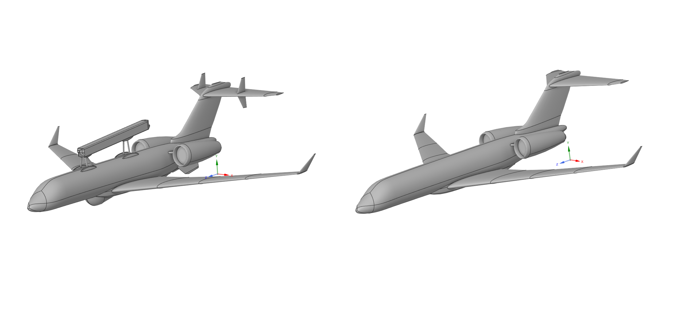
So the wings are completely redone from scratch. The airfoil for the wings is just some generic airfoil, since the model will not be used for any aerodynamic analysis, it felt unnecessary to spend time on getting the profile correct. Also removed the fan blades and plugged the engine (as per recommendation) to facilitate for the upcoming analysis.
Raymer
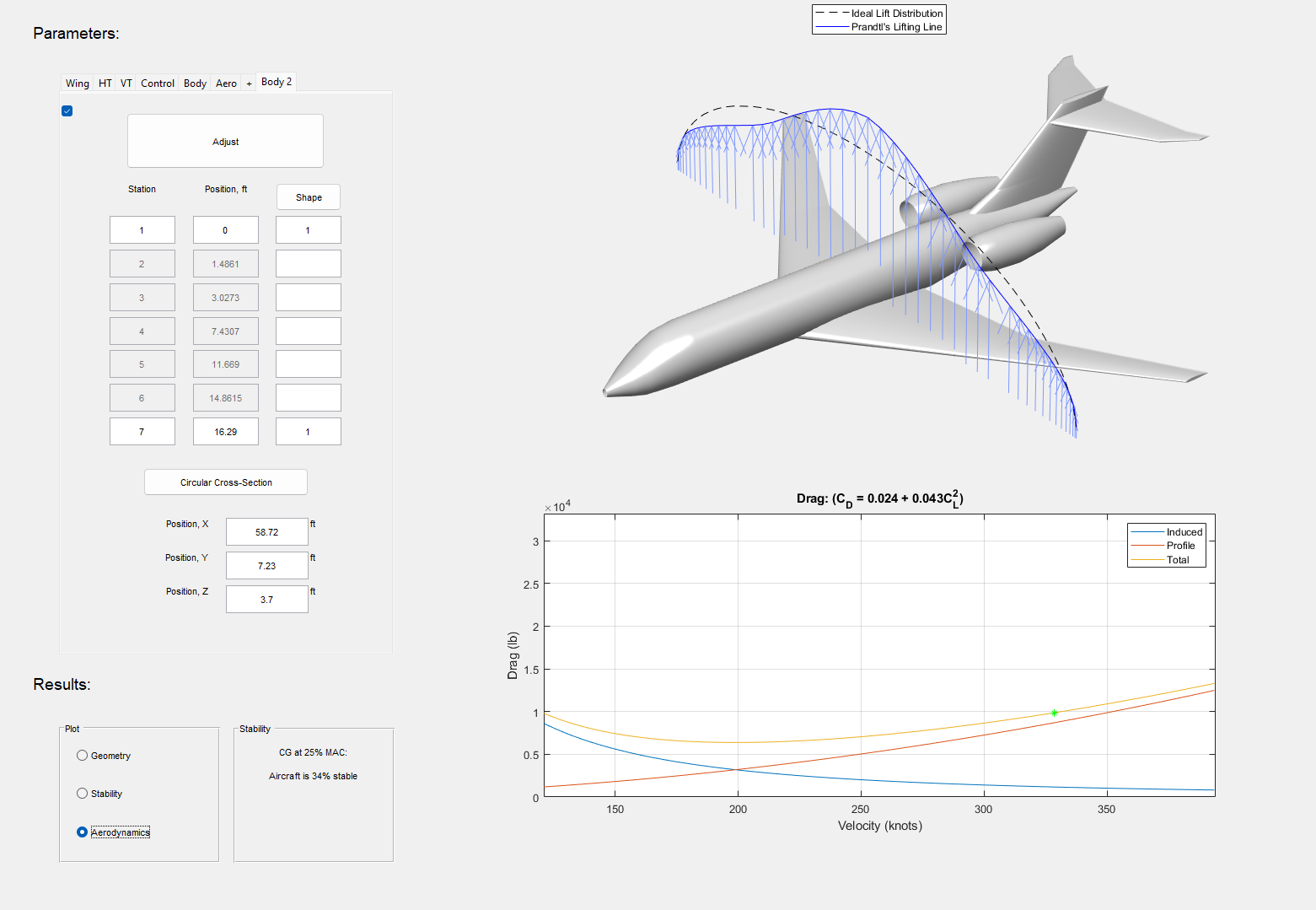
Calculation-wise I have gone through the methods from Aircraft Conceptual Design by Raymer for estimating drag. Mostly to have something to compare to later on. I've used both the Equivalent Skin Friction and the Component Buildup-Method. For the parasite drag (zero-lift drag) I've ended up with 0.0128 and 0.0098. The values I get are quite low, especially the second one, so I guess I will go through the code once again and re-check If I got all the dimensions correct.
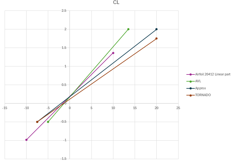
In order to estimate the drag I need to include the induced drag as well. This is a bit tricker since the induced drag depends on how and with which angle of attack the lift is generated, large angle of attacks (high lift coefficients) will generate large vortices and thus higher induced drag. But assuming the lift curve (lift coefficient versus angle of attack) is linear I can make some crude approximations which are probably good enough for small angles of attack (in the linear part of the lift curve, when approaching angles closer to stall, the approximation is not valid).
I've also tried to cross-reference my results with a software called Piano. I've just tinkered with it for a day. But it seems to rely heavily upon Raymer[1] and Tornbeek[2] for its estimations due to some references scattered around in the software. But I'm not really certain at how it could help me at this point. But after a quick glance comparing the envelope the software creates compared with some data for the Global 6000 manual, it seems like the methods for estimating is not that for off. I could probably use it for sanity checks in conjunction with the Raymer calculcations.
Setting everything up
Never under estimate the time to get settled in. Getting access to computers, software, network and peripherals do take some time. I've had a couple of runs up and down the stairs and harassing the IT department.
But now I have a computer, a dock, two screens, a wired network connection and a mouse. I have access to a virtual (linux) machine and access to one workstation/calculation computer, but so far I only have gotten command line access (no GUI, since I'm just getting erros when trying to connect).
And for the first time I'm feeling a bit stressed. There is a ton of things to do, and my time estimates has so far been quite off. Something that seems really simple usually takes three times as much times due to some weird errors or unforseen problems.
Week 14
This week has been mainly about setting up TORNADO, which I had some problems with at first. I think it might have to do with either OneDrive for work or that the name includes Swedish characters.
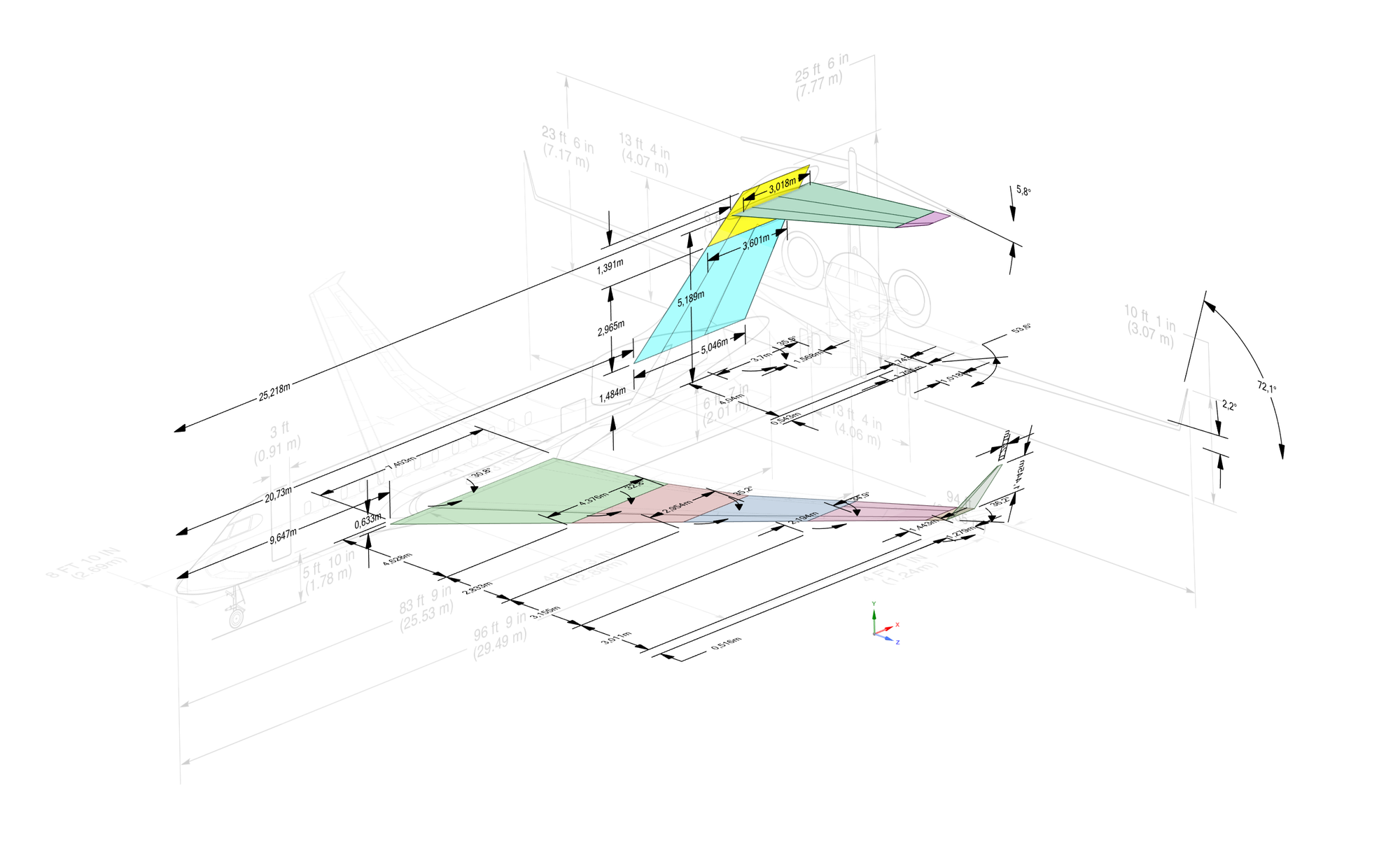
For the geometry, I quickly realized there were a lot of numbers to keep track of, so I created a CAD model with the planned panel layout and used the drawings from the aircraft manual as a reference. With that, I could fairly easily view all the relevant data (location of aerodynamic surfaces, span widths of the sections, sweep angles, and dihedral) and gather them all in a spreadsheet.
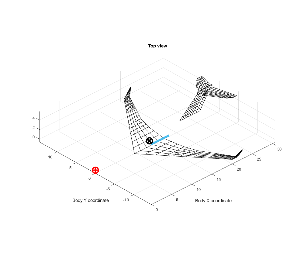
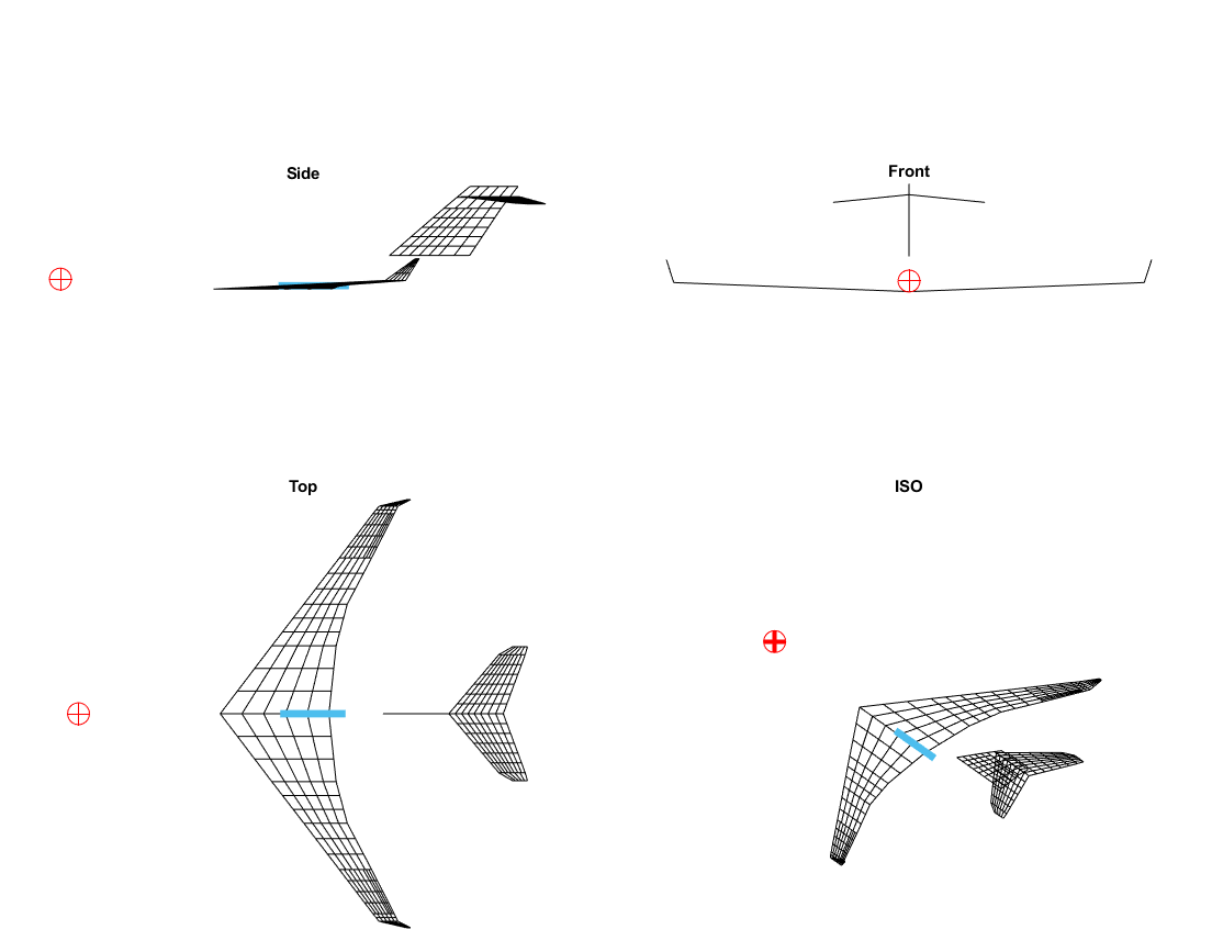
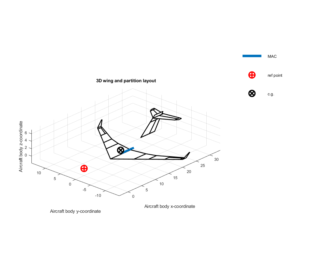
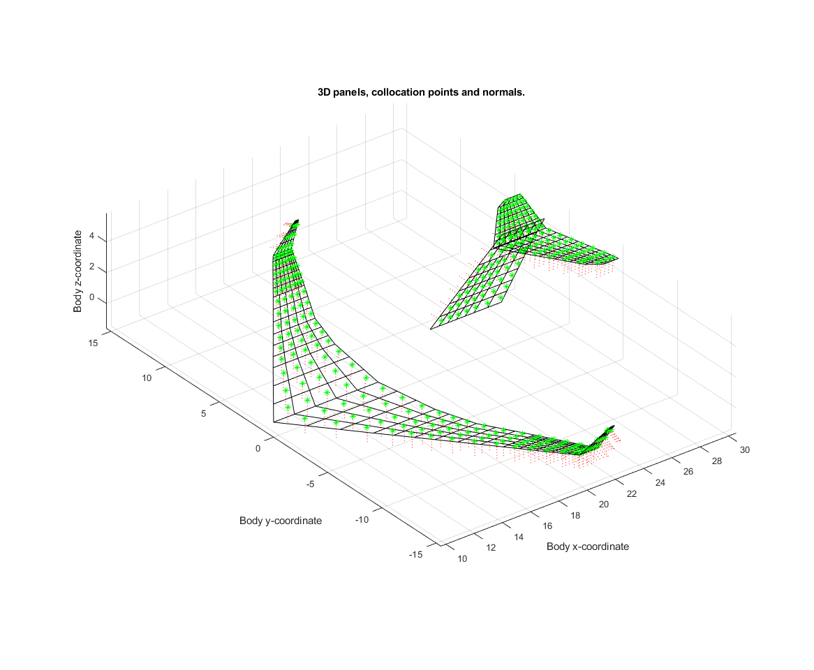
Screenshot of the geometry plot output by TORNADO (MATLAB). The nose was used as a reference point and the CG was just set to an arbitrary (but not unreasonable) value.
Questions and concerns
How thorough should I be with the geometry and dimensions? Looking at the front section for example there seems like there is more dihedral at the root and less at the tip. As it is now, I just took some kind of average (~2.2 degrees). Another example is the washout, it is difficult to estimate from drawings and picture, as of now it is zero.
My take now is that in the grand scheme of things, and with the accuracy of the models and with the end result in mind, this kind of optimisations is unnecessary, and the current geometry accuracy is enough.
But of more concern, and the impact it may have on the results is the airfoils. On the UIUC Airfoil database [1] it seems the Bombardier Global Express (predecessor to the Global 6000) uses the Canadair 11% for wingtip and the root. However, I haven't found the coordinates for that particular profile. But I dit notice that there is an (Bombardier) CRJ900 file in the aircraft folder for TORNADO. The CRJ900 also utilizes a supercritical wing [2] with a profile from the Canadair-series of airfoils. The particular model in the TORNADO folder uses the SC20410[3]. I don't know the background of the data for that model, but that profile at least has the supercritical-look to it and is probably a good approximation for the Canadair 11% for the main wing.
For the empennage I have used a symmetrical NACA0012 profile. Assuming a symmetrical airfoil is reasonable (especially for the vertical stabiliser), but the thickness-ratio of 12% might be on the thicker end for this type of aircraft?
Contribution of the fuselage and the GlobalEye-specific modifications? How should they be modelled, or should I even add them?
Week 13
Meetings Tuesday and Wednesday.
The first meeting was regarding the radar cross section (RCS). I could only show images of the CAD model since apparently, the student version of Ansys SpaceClaim doesn’t allow exporting to other file formats. However, based on the feedback from the image, it seems like the model will be good enough. I will make it even less detailed by changing the engine intake and exhaust to flat plates and removing some features (windows, doors, etc.).
The second meeting was a walkthrough of the TORNADO program and code. The most pressing concern right now is how to get the geometry correct in TORNADO.
The third meeting was where I received a description of the models used and how to convert them for use in the simulation environment. The Pseudo 5-DOF flight model is written in MATLAB and can be tested with commands, with the output in plots. When ready for delivery, it will be exported to C++ (with Matlab Coder); some manual edits are required to get it working, though I didn’t have to concern myself with that since I would get assistance with it.
I’ve not yet fully grasped how the Pseudo 5-DOF model actually works, but I’m working my way through Zipfel’s book on Modeling and Simulation of Aerospace Vehicle Dynamics, and with some aid from the department, this will eventually sort itself out in time.
We also discussed how the data for the radar cross section/signature should be formatted. Essentially, the resolution could be quite coarse, and an analysis of a certain frequency could represent a wide spectrum of frequencies. Therefore, there will be no need to run a multitude of different setups.
And for the visual representation, basically any common CAD/3D-model format would be acceptable.
Week 12
I’ve been mostly working on editing the CAD model. I’m not that proficient in CAD modeling; most of my experience with modeling has been with simple geometries used in basic courses for stress analysis or simple wings. This task was a bit more challenging, and it involved software with which I have little to no experience. However, with the help of a scaled CAD model of the Global 5000, YouTube, and some Ansys tutorials, I think I have created something that will hopefully be good enough for the RCS (Radar Cross Section) analysis and, in the worst case, will suffice as the visual model in the simulation.
At first, I had some difficulties scaling the model due to the way it was constructed; a simple pull/scaling just resulted in an error. I eventually solved it by splitting the model into wing, fuselage, and empennage sections and removing some of the interior elements. Since the Global 6000 is longer than the 5000, I split the fuselage aft of the cockpit, moved the cockpit to the correct location, and extruded the fuselage to fill up the gap.
Introduction and Week 6 - 11
This is my mandatory reflection document for my master’s thesis course. Since I’ve only recently learned that a reflection document is needed, this will serve as an introduction to the project and what I have been doing up to this point.
The project aims to implement a flight model for the Global 6000 / GlobalEye in an aerial combat simulation environment. To summarize, the model consists of three parts:
- Aero data for estimating the flight characteristics, including various coefficients (such as lift, drag, stability derivatives, mass moment of inertia, center of gravity, etc.), which is the main focus of this project.
- Engine performance, important for the model to be representative of the real-world counterpart in the simulation, especially in regard to speed, acceleration, and fuel consumption (and thus endurance).
- Radar Cross Section (RCS), necessary for the model to be targetable in the simulation environment.
For the project itself, the reports (planning, half-time, and final) and presentations (half-time and final), along with the reflection document, are of course important and vital parts of the project.
Initially, the main work was focused on assembling the project and managing the administration surrounding it, both from the university side (getting approval from the university, registering for courses, finding an examiner, supervisor, and opponent) and from the Agency and the various departments involved in the project. I’ve also tried to get hold of a POC with the manufacturer to hopefully obtain some more detailed reference data.
I also tried the MATLAB plugin, Aircraft Intuitive Design Tool. Unfortunately, it hasn’t been updated for a while, and the error frequency is quite high. However, it is useful for quickly generating geometry for DATCOM-based tools.
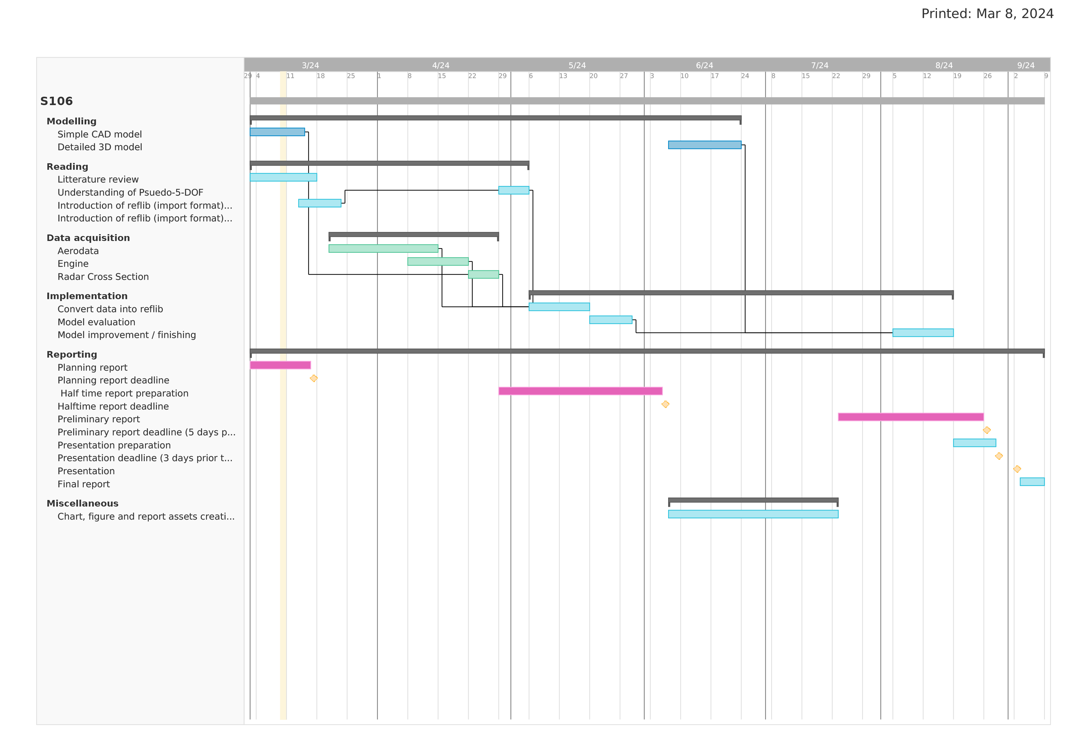
I’ve also submitted the planning report, where I have set up the main body of the report and decided which sections to include. One thing is certain about that report: it will be subject to change. The main takeaway from that report is probably the Gantt chart and the timeline.
I have also done some initial reading regarding flight simulation software and
tried to refresh the little knowledge about flight dynamics I have as well as get some more information [1].
I would say that the project really got started in Week 9 with the first on-site meeting at the agency, where I could obtain more tangible stuff to actually start working with.
Flight Simulation Software by David Allerton and Airplane Flight Dynamics and Automatic Flight Controls by Jan Roskam ↩︎